by Crutschow
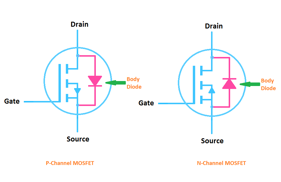
Yes, power MOSFETs have a parasitic diode called Body Diode. As a result of this diode, a single MOSFET can work only as a unidirectional switch. A single MOSFET can't switch-off the opposite direction, because the diode conducts independent of the gate. The body diode is usually fairly slow to turn on. The MOSFET can only carry positive current (n channel Mosfet, from drain to source). If the load is inductive, there are times when the switch (MOSFET) must be on, but current flows in the oposite.
When you parallel a battery with another battery or other source, the batteries are often required to be back charged. This can be done with standard diodes, but that gives close to a half volt drop — even with Schottky diodes. This is especially problematic with low-voltage batteries, where that drop is a significant percentage of the battery voltage, noticeably reducing efficiency and battery life.
To minimize this forward drop you can configure a MOSFET as an ideal diode, which has a very low drop in the forward direction (equal to the current times the MOSFET's ON resistance) while blocking the current in the reverse direction.
Below is the LTspice simulation of a simple ideal-diode MOSFET circuit. It uses inexpensive components consisting of a P-MOSFET (for use in the positive rail) with a dual PNP transistor and two resistors.
Mosfet With Diode Symbol
Q1 and Q2 form a current mirror circuit. The indicated values of R1 and R2 cause Q2 to be on and thus M1 off (Vgs ≈0V), when there is no voltage difference between the drain and source of M1. The mirror has a gain of ≈130 from the voltage difference between the two emitters to Q2's collector voltage change.

In the forward direction (output voltage lower than the battery voltage) the current mirror becomes unbalanced due to the difference in emitter voltages, such as to turn Q2 off, which puts the P-MOSFET gate near ground potential, turning it on. This allows current to flow from the battery to the output (left to right) with a low drop. (MOSFETs conduct equally well in either direction when on.)
When the output voltage becomes slightly higher than the battery voltage, this voltage reversal across the MOSFET unbalances the current mirror in the opposite direction, causing Q2 to turn on. This causes the MOSFET gate voltage to rise, reducing Vgs [V(G,Out) in plot], which turns it off and prevents reverse current flow.
This can be seen in the simulation, as the current only goes out of the V1 battery when the V2 output voltage is lower than the battery voltage, and doesn't flow in the reverse direction when the output voltage is greater than the battery voltage. The maximum voltage drop, when the battery is providing 2A current is ≈32mV with the MOSFET shown, demonstrating the near ideal diode operation.
How Does A Mosfet Work
The current mirror operation is very sensitive to any offset between the two transistor base-emitter voltages, which could possibly allow some current conduction in the reverse direction. It is thus recommended that a matched transistor pair be used, such as the DMMT3906W shown on the schematic (basically two 2N3906's in one package), which have their Vbe matched to within 2mV max and are thermally connected.
(The simulation was done with 2N3906‘s which are perfectly matched in the simulation, unlike real life.) The DMMT3906W pair are quite inexpensive, selling for U$0.37 here, for example.
The P-MOSFET selected should have an on-resistance small enough to give a low voltage drop when conducting the maximum battery load current. If the battery voltage is less than 10V then a logic-level type MOSFET should be used which have gate-source threshold voltages (Vgsth) of less than 2V.
One of these circuits can be used at the output of each battery; however, many are in parallel.
You can read more articles by Electro-Tech-Online 'Well-known' member, Crutschow, here.
